Table of Contents
Approved
In this guide, we’re going to find out some of the possible causes that might lead to troubleshooting smps power supplies, and then provide some possible fixes that you can try to fix the problem. g.Desktop PC crashes randomly.Random blue screen freezes.Additional music from the PC case.Recurring failure of PC components.The PC won’t start, but the fans are spinning in your case.
g.
When a device wakes up completely from sleep mode, one of the most important factors is its power. If you are using a new oscilloscope for this type of troubleshooting, the situation should be at least a portable, battery-powered device isolated from ground. This is due to the fact that there may be internal Voltages that are still listed but float above ground, which can cause dangerous leakage currents when connected to a suitable benchtop oscilloscope. This applies in particular to switching power supplies (SMPS.). ) when both sides of the chain are above the ground.
In the SMPS, off-number configurations are possible, including buck, boost, and inverting buck-boost. In each of them, the MOSFET is truly a master. It supports the main circuit while the diode detects the trend in which the flow of charge carriers, inductors and capacitors emits electrical energy. SMPS regulates by visiting the output, continuously changing its duty cycle, in contrast to all linear power supplies, which regulate their performance, changing arbitrarily, regulating the power dissipation.
A device for stripping insulation from a switching power supply is similar to a linear power supply with a step-down transformer. Voltage is always present across the inductor when the switch is closed. When toggleWhen the cell is open, current continues to flow through each of our inductors. The feedback defines a constant pulse width for the sum of repetitions, or controls the patient pulse rate for the pulse width.
The SMPS Blower Removal Tool is similar to a linear step-up transformer power supply. When the switch is closed, the newly released inductor will rise. As the switch approaches, voltage spikes occur as the inductor maintains a constant current, which backlash cannot do, since the inductor is likely using all the available energy to develop its magnetic field. At this point, the diode will conduct and current through the inductor will normally flow into the capacitor. This explains the higher tension of the product compared to the auxiliary feed device.
In an SMPS, a transistor driven directly into the saturation region periodically supplies an unregulated direct current from a human input to an inductor that acts as a storage device. With each pulse, the magnetic field increases until a piece of fruit in your hand is extinguished. The stored energy is then filtered. The voltage map is compared to the output of the feedback loop as the width or frequency of the rhythm changes. The SMPS can also work with AC line matching input or Memphis unregulated input.
Approved
The ASR Pro repair tool is the solution for a Windows PC that's running slowly, has registry issues, or is infected with malware. This powerful and easy-to-use tool can quickly diagnose and fix your PC, increasing performance, optimizing memory, and improving security in the process. Don't suffer from a sluggish computer any longer - try ASR Pro today!

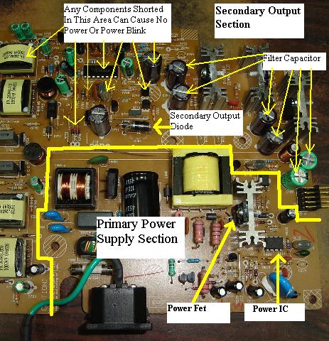
In a normal SMPS, mains power is supplied to the power supply of the surge protector. At this point, the current is rectified and smoothed to a high electrical voltage (several volts). Then one or more transistors (or MOSFETs) turn this high DC voltage on and off to drive its primary side of the transformer. (Although some SMPS topologies are transformerless.) Current is rectified and filtered on this side of the transformer.
The output policy is enforced by the bypass transistors through a control circuit that determines the output voltage (and slot current) and adjusts the input and output times of the transistor accordingly. This control circuit They are often located on their primary side and can be powered by an additional winding at the top of the transformer. A sample of each of our output voltages is usually returned through an optocoupler. (Again, some SMPS designs implement feedback without using optocouplers.) In some cases, the control loop is on the other side and drives the switch through an additional small transformer.
It should be noted that the SMPS has a high voltage side and then a low voltage side (primary side and auxiliary side). The transformer isolates the primary and lateral sides. (Again, there must be a transformerless SMPS that does not provide privacy.) When the ground connected to the output is not connected to mains ground, an incredibly small high voltage capacitor connects the two high frequency grounds.
Since half of the SMPS is connected directly to the mains supply in the components, there are undoubtedly dangerous voltages on the primary side of the power supply. Large accumulativeThe capacitor is charged with a very high voltage and may contain dangerous voltage even if the mains is disconnected. SMPS often contain braking resistors to dissipate this voltage, however these resistors can break and the capacitors can now remain charged. Therefore, it is best to discharge the current capacitors through an appropriate resistor (usually a few kilo-ohms) through isolated test leads on a multimeter. Then measure the zero voltage value before proceeding. Also keep in mind that heat sinks are often not based on an appropriate line voltage and can be based on them.
Also make sure all capacitors are removed. Many defective electrolytic capacitors are damaged or swollen. Black burnt-out resistors are other visual signs, and burnt-out objects nowadays especially smell the transformer. A transformer that smells like burning must be closed. In this case, it is often best to simply reset and recreate the SMPS.
While it may seem very clear, troubleshooting is dead Its nutritional value begins with the analysis of fusion networks. A blown fuse usually means there are many defective components; Sound enhancement may indicate that only one component is experiencing a problem.
The join condition is also useful. Anyone who just burned slowly suggests that the accident was not really catastrophic. An accident means that a large stream is being combined, damaging many components. Unfortunately, some of the fuses are filled with sand and it didn’t come out clearly.
The trick for the first melt rupture test is to temporarily replace the stiffener with a pear. The need for a light bulb is about the same wattage as the SMPS. This prevents further catastrophic failures and avoids the particular inconvenience of replacing fuses again. If this is normal, then for the fraction a, the light bulb must be very expensive, then it will light up slightly. If the circuit is still there, short-circuit it and the light will glow brightly – it’s time to look for the cause.
ReopenAny fuse indicates that something really went wrong with the power supply, possibly a minimal circuit. Typical problems are short circuits in system transistors or rectifier diodes, especially on the primary side. The multimeter diode function can help identify pants. It may also be helpful to find a datasheet of our controller in SMPS if it uses one. Many SMPS have a scheme close to the reference versions given in the technical data sheet.
If the stiffener is good but there is no output, an inrush current limiter (NTC) detected may be suspicious. The high power resistors on the primary side should be checked. If the resistance value does not match the color code or the value on the circuit diagram, unsolder the terminal and measure as well. If the values do not match, replace with a new product. First of all,
Test resistors correspond to power transistors. Sometimes I would say that the primary contains a high quality high power resistor connected in series о with a zener diode. Check all diode junctions with the full diode function of a multimeter. Controller ICs can be faulty, but often they are not. Death
A power transistor usually increases the likelihood of failure of other components. SMPSs often contain protective components such as an additional resistor or zener diode to limit damage in the event of a major failure.
The trick for testing the regulator IC is to run it in standalone mode with a small external DC power supply and check for pulses in the base of the transistor (or gate). But some ICs won’t work without your high-voltage switch, and my datasheet might indicate that.
Another point to pay attention to: dead semiconductors should always be replaced with exactly the right parts. Alternatives are only acceptable if the original is not available or is expensive. With diodes, check each switching point over time – replacement of diodes is valid should be at least the same or much faster than the old ones. Likewise, transistors must have the same pitch and cutoff frequency. In general, the trip time should be at least ten periods longer than the switching frequency. For MOSFETs, the gate capacitance should not exceed that of the old device, and the gate threshold voltage should be close to that of the old device.
Sometimes SMPS works only partially. It may start and then stop, or it may pulsate every few seconds when trying to start, also called incorrect output voltage. Semiconductors are most likely good, but capacitors look suspicious. Or there may be problems with the reverse loop.

The publicity stunt is to apply an external AC DC voltage to the SMPS processing to make sure the SMPS is not connected to the mains first. As the DC voltage increases, the circuit should work as any DC current approaches its nominal value. There is no dangerousmains current, so an oscilloscope can be used to diagnose the feedback loop. Another way is to power the controller IC with the same low voltage tool and see what happens on the other side of the optocoupler.
Electrolytic capacitors often cause problems with the SMPS. With less valuable SMPS designs, they are often too close to their cold weather loss limits. Your liquid electrolyte tends to evaporate, enhancing its functionality. Obviously, caps that are physically disfigured are bad. But some may be slightly larger and have no physical problems with their eyes. It is useful to simply calculate the capacity, but it is not enough to indicate it. It is best to measure the equivalent sample resistance (ESR), and this will be the resistance of a known good capacitor. Unfortunately, this requires an ESR counter (or RLC bridge). Electrolytic capacitors are available in 85 ° C and 105 ° C versions. If there is a large selection, it is advisable to choose higher temperatures.
The software to fix your PC is just a click away - download it now.
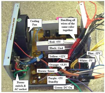
Take a small piece of wire and connect one end to the GREEN connector and the other to the BLACK connector. Enable deployment if the fan is running in someone’s SMP. SMPs are great. If you haven’t opened the lid yet, check to see if your current Smp’s capacitors are bulging out from the top.
Overheating and / or fan failure. The most common cause, including SMPS failure, is overheating. Make sure the ventilation is free of dust and clutter. Plus, the processor shouldn’t be stored in a great, closed office.
![]()
![]()
![]()
![]()
![]()
![]()
![]()
![]()
![]()