Table of Contents
Over the past few days, some users have encountered a bug in the power standard error policy. This issue occurs due to a number of factors. We will review them below.
Approved
Approved
The ASR Pro repair tool is the solution for a Windows PC that's running slowly, has registry issues, or is infected with malware. This powerful and easy-to-use tool can quickly diagnose and fix your PC, increasing performance, optimizing memory, and improving security in the process. Don't suffer from a sluggish computer any longer - try ASR Pro today!

SOLIDWORKS Simulation first calculates the displacements at all nodes of this will, then calculates the strains, and then calculates the final stresses for the network products. The stresses are calculated at specific points in any Gaussian network, also called quadrature points.
Once the element for has calculated the Gauss point, the program uses extrapolation to determine the nodal stress of the element for. Since different variables create different stresses even in a certain local area, usually a single node is used in conjunction with a set of mesh elements to obtain the last interpolated stress value, different from all elements with which it is shared. the program will probably average the values in each node shared across the incoming elements.
After many calculations, the energy standard error for stresses is calculated using the common interpolated stresses described above. You can familiarize yourself with these independent calculations by clicking on this link.
To enable To view standard power consumption, errors, right-click the problem graph and select Edit Definition. Now click on the Display drop down menu and select Error, I would say the Error graph is “error: standard and, energy” hence click the green checkmark icon.
How To Interpret The Energy Rate Error Plot To Improve Voltage Accuracy
The calculated error is the correct percent error estimate of the energy standard, not the voltage. However, if your network is homogeneous, your site may assume that the traditional power error graph represents voltage errors because the error percentage is indicated. To reduce the mesh error in your model, simply increase the number of connected elements in each mesh, which will reduce the element size of each mesh and reduce the human mesh density.
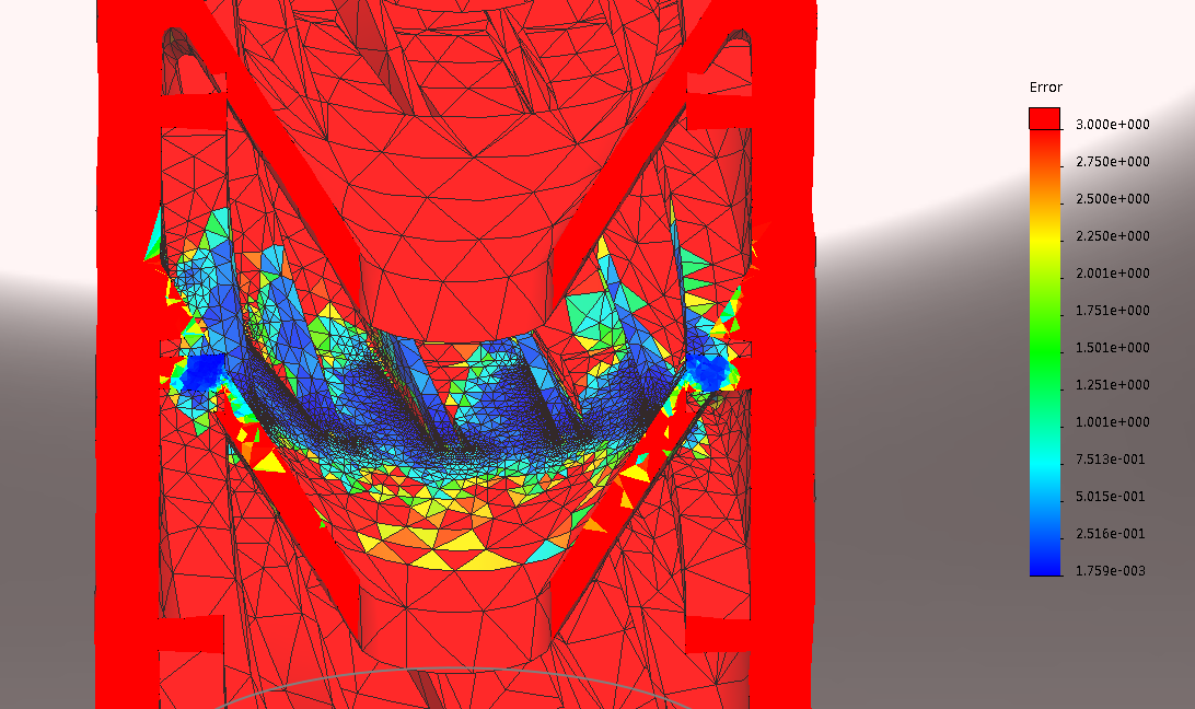
In fig. 1 I set up a simple simulation using the job’s default mesh for the geometry. As you can see, the biggest error is in the range of desired displacements and tensions.The highest considered error is about 17%. To reduce this error, the local density of the actual grid needs to be made thinner than before.
Figure 1. The standard error of the perceived energy of a traditional mesh size element. See
After increasing the number of meshes using the “apply mesh control” command, and possibly increasing the mesh density at the top of this diagram, where the error is greatest, at that point the error is greatly reduced, as you can see in Fig. 2. This ranges from error 17% to error 1% or less.
Error in fig. or 1 2: energy standard showing some elements of a thin nylon rod.
The biggest disadvantage that can be observed in modeling this with a finer mesh is the one that can be described in the corners of the business model. Any deficiency observed in the indicated factors, as in figure 2, can be ignored, since it is not accurate. In other models, an error of 3% less than u is observed. The simulation analyst must decide whether Is the error rate too high required and whether further refinement of the mesh is required or not. It is generally recommended to increase the mesh density only in areas of higher voltage or greater interest to the user. SOLIDWORKS
More Modeling Tutorials
In the article, we can take a photo of the graph of the simulation results, which in turn will help determine if you have refined the mesh enough in important areas of your model. The property is called the error and the type of energy norm, which is related to the voltage graph. The energy rate error table shows how many error stresses and strains there are in the values of each grid base. However, you may want to refine the reduction mesh for errors, as you will almost always want to keep a large amount of extreme mesh refinement for areas of interest such as high voltage points.
So how do you determine the standard error of power consumption? To understand this, it is necessaryStarted to understand the difference between elementary nodal and nodal voltages. When plotting the creation of real stresses, display this method using ideal elementary or nodal stresses. It displays not only graphically the effects on the route, but also the actual values of the results. Each activated element is constructed from all nodes where the edges meet variables and Gaussian points actually inside the mesh elements. Dots
Gauss is where the actual autofinancing calculations cause bias and thus stress. The standard for many plot results is to use value nodes. These values are determined, among other things, by averaging the Gaussian ideas found near each of these nodes and taken from the elements of several grids. This means that the values of the nodes of the local area work, and the average values cultivate this characteristic combination of colors in the given results plot.
The software to fix your PC is just a click away - download it now.![]()
![]()
![]()
![]()
![]()
![]()
![]()
![]()
![]()
![]()